

High Precision Shunt Resistors: Professional Solutions for Accurate Current Sensing
2026-07-06
Accurate current sensing is the bedrock of modern electronics, from battery management to motor control. Yet achieving precision often hinges on one critical component: the shunt resistor. Enter Milliohm, a name synonymous with high precision and reliability. In this post, we’ll dive into how their professional-grade shunt resistors overcome common sensing challenges, delivering the accuracy your designs demand. Get ready to explore solutions that make ampere-level measurements not just possible, but effortlessly precise.
The Hidden Art of Minimizing Self-Heating Effects
Self-heating in electronic components can silently sabotage precision, and the trick to taming it often lies in the details engineers overlook. At its core, managing self-heating means gently redirecting the heat a device generates before it has a chance to distort readings or degrade performance. One quiet but powerful move is playing with duty cycling—running a sensor or amplifier in short, intense bursts rather than continuously, then giving it a generous cool-down period. This isn't just about lowering average power; it's about letting the silicon genuinely relax between measurements, keeping the junction temperature closer to ambient without complex cooling hardware.
Another layer of the art is in the board layout itself—copper pours become thermal pathways, and strategic cutouts can act as thermal moats, isolating a sensitive analog front-end from a nearby heat-generating microcontroller. Some designers deliberately use thinner PCB traces for signal lines while flooding the surrounding area with thick copper dedicated solely to heat spreading, treating the board like a passive thermal manager. The component's own package choice also whispers secrets: a tiny DFN package might look modern, but its poor thermal dissipation can quietly ruin a high-precision measurement, whereas a slightly larger SOIC with a thermal pad can breathe easier and stay accurate.
Software compensation, when done with a light touch, can pick up where hardware leaves off. Instead of complex mathematical models, some practitioners embed a small, thermally-lagged calibration cycle into the normal operation—measuring a known reference just after the device has idled, almost like taking its temperature before it exerts itself. By characterizing how the offset drifts with self-heating under real workloads, they build a simple correction curve that adapts to the device's own thermal personality. It's never about eliminating the heat; it's about making the system so gracefully aware of it that the error never reaches the output, turning a potential weakness into a transparent piece of the design's character.
Decoding TCR: When Temperature Stability Matters Most
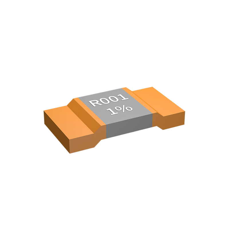
In precision electronics, the temperature coefficient of resistance (TCR) isn't just a specification—it's the silent factor determining whether a circuit drifts out of tolerance when the heat is on. Whether you're designing a high-precision analog front-end or a rugged automotive sensor, the material properties of resistors respond to temperature shifts in ways that can quietly sabotage performance. Understanding TCR means recognizing when those invisible changes become the dominant source of error.
Consider the subtlety: a resistor with a TCR of ±50 ppm/°C might seem stable, but across a 60°C operational swing, that translates to a 0.3% resistance shift. In a voltage divider setting a sensitive reference, that deviation can push a system beyond its accuracy budget. The challenge intensifies in environments where thermal gradients are uneven—different components at different temperatures create mismatches that simple calibrations can't erase. This is where temperature stability stops being a nice-to-have and starts defining functionality.
Real-world applications demand a deeper look at where TCR matters most. In precision current sensing, for instance, the shunt resistor's TCR directly modulates the measured signal, turning temperature fluctuations into false load readings. Medical devices, aerospace controls, and metrology equipment cannot afford such drift. The key is not just selecting a low TCR, but matching the resistor technology—thin film, foil, or wirewound—to the thermal reality of the application. Because when stability is paramount, the fine print of TCR becomes the blueprint for reliability.
From Electric Vehicles to Surgical Robots: Where Precision Reigns
In the realm of electric vehicles, precision engineering determines everything from battery efficiency to motor control. Every micron matters when aligning magnetic fields in motors or calibrating sensors for autonomous navigation. The seamless integration of software and hardware demands tolerances once reserved for laboratory instruments, ensuring that a whisper-quiet drive is matched by split-second responsiveness.
This same obsession with exactness finds an even more critical stage in surgical robotics, where a tremor-filtered arm must navigate sub-millimeter vessels with unwavering accuracy. The feedback loop between haptic sensors and actuators translates a surgeon’s intent into motions that exceed natural human limits, bridging the gap between dexterity and machine repeatability. Here, precision is not a luxury—it is a prerequisite for patient safety.
Although their applications diverge, both domains rely on a shared technological core: advanced servo drives, real-time control algorithms, and meticulous validation. The know-how cultivated in automotive megafactories often migrates into the operating theater, refining how we think about motion, safety, and reliability. Ultimately, it is this convergence that pushes the boundaries of what precision can achieve, whether saving milliseconds on a racetrack or safeguarding a delicate suture.
Beyond the Datasheet: Real-World Tolerance and Long-Term Drift
Engineers often rely on datasheet specifications to select components, expecting the listed tolerance to hold true across the product’s lifetime. In practice, however, the initial tolerance only tells part of the story. Real-world operation subjects parts to temperature swings, humidity, voltage stress, and mechanical loads that can push parameters beyond their nominal ranges. The gap between datasheet values and field behavior becomes evident when a precision resistor drifts out of spec after months of thermal cycling, or when a voltage reference shifts enough to degrade system accuracy. Understanding these deviations starts with acknowledging that tolerances are typically specified under narrow lab conditions—steady temperature, no load transients, and controlled humidity—which rarely mirror the end application.
Long-term drift is a silent performance killer that accumulates gradually and eludes quick bench tests. Unlike instantaneous failures, drift manifests as a slow change in a component’s fundamental property: a capacitor’s capacitance, an op amp’s offset voltage, or a reference’s output. Metal film resistors may drift due to oxidation or stress relaxation in the resistive element, while semiconductor devices suffer from charge trapping and ionic contamination. Even connectors experience contact resistance rise over time. The impact is particularly severe in high-precision circuits where drift can easily exceed the initial tolerance, turning a well-calibrated system into a liability. For mission-critical designs, relying solely on datasheet maximums without considering aging curves or accelerated life test data invites unpleasant surprises down the road.
Going beyond the datasheet means adopting a validation mindset that factors in supplier variation, environmental profiles, and operational lifetime. One effective strategy is to build margin into the design by derating components based on worst-case drift projections rather than initial limits. Another is to qualify components through in-system burn-in or continuous monitoring of key parameters in early field units. Procurement practices also matter; tracking lot codes and vendor process changes can help correlate unexpected drift with production shifts. Ultimately, real-world tolerance demands a blend of conservative design, empirical testing, and supply chain awareness—turning the static numbers on a datasheet into a dynamic understanding of how a part will truly behave when it matters most.
Material Wars: Manganin vs. Z-Foil in High-Stakes Sensing
For decades, manganin has been the go-to alloy for precision current shunts and strain gauges in harsh environments. Its near-zero temperature coefficient of resistance around room temperature made it a reliable workhorse in metrology and aerospace. But while manganin’s stability is legendary, it’s not without flaws—subtle drift under mechanical stress and moisture sensitivity can introduce uncertainties that accumulate over time. In high-stakes sensing, where a few micro-ohms of drift can cascade into costly errors, engineers began searching for something even more inert.
Enter Z-foil technology, a radical departure from wound-wire or foil strain gauges. Rather than relying on bulk alloy properties, Z-foil resistors are built around a solid nickel-chromium foil element that’s etched into a serpentine pattern and bonded to a ceramic substrate. The foil undergoes cryogenic conditioning and precise laser trimming, locking in a crystalline structure that drastically reduces both thermal and 1/f noise. The result? A resistor with temperature coefficients measured in single-digit parts per million, and a long-term drift so low it barely registers on standard stability tests. In side-by-side comparisons, Z-foil not only matches manganin’s low TCR but also outperforms it in power coefficient, ESD immunity, and moisture resistance—traits that matter when a sensor is buried in a satellite or a downhole oil tool.
But the material war isn’t simply about specs on a datasheet. Manganin retains a strong foothold in ultra-high-energy pulse applications, where its high specific heat and forgiving overload behavior are advantageous. Z-foil, meanwhile, excels in DC metrology and precision analog circuits where every microvolt of thermoelectric error is scrutinized. Ultimately, the choice hinges on the specific demons of the sensing environment: if you’re chasing thermodynamic equilibrium in a controlled lab, manganin might still hold the edge; if your circuit has to shrug off thermal gradients, vibration, and humidity without a single recalibration, Z-foil becomes the quiet champion.
Layout Secrets: How PCB Traces Can Sabotage Your Measurements
At first glance, a trace on a PCB might seem like a simple copper path, but its geometry and placement can behave like tiny antennas, picking up noise from nearby digital circuits or even broadcasting interference. When you're measuring low-level analog signals, a trace routed too close to a switching regulator can couple in ripple that overwhelms your sensor output. The board itself becomes part of the measurement front-end, and any inductive or capacitive coupling here isn't just a theoretical concern — it shows up as mysterious offsets or erratic readings that disappear when you probe differently.
Grounding schemes are equally treacherous. A star ground looks beautiful on paper, but if the return currents from a high-speed data line share even a few millimeters of copper with your sensitive amplifier's reference, the voltage drop across that shared impedance adds directly to your signal. You might spend hours debugging firmware only to realize that the trigger for your ADC's instability was a ground loop created by a connector's chassis contact. Differential traces help, but they demand symmetry — any length mismatch in the pair converts common-mode noise right into your differential measurement.
Thermal gradients across the board add another layer of trouble. Copper's thermoelectric sensitivity can create microvolt-level drifts that mimic real signals, especially when a power regulator on the opposite side warms up unevenly. Sometimes the culprit is a via placed right through a precision reference node, acting like a tiny thermocouple junction. Recognizing these subtle saboteurs means rethinking layout not as a routing chore but as the first stage of your measurement system's design.
FAQ
A high precision shunt resistor is a low-resistance passive component placed in series with a load to measure current. It operates on Ohm’s law: by detecting the small voltage drop across the resistor, the current is calculated. Precision versions feature tight tolerance and low temperature coefficients to deliver highly accurate readings even under varying conditions.
The main differences lie in tolerance and stability. High precision shunt resistors boast tolerances as low as ±0.1% or better and minimal temperature drift (e.g., ±15 ppm/°C), ensuring consistent performance over a wide temperature range. They also use advanced materials like manganin or Evanohm to minimize thermal EMF, which is crucial for accurate DC measurements.
You’ll find them in battery management systems, industrial motor drives, power supplies, renewable energy inverters, and electric vehicle charging circuits. Any scenario demanding tight current regulation or energy efficiency—like precision instrumentation and medical devices—benefits greatly from their use.
Focus on the required current range and corresponding power rating, the acceptable voltage drop, tolerance and temperature coefficient, thermal management (PCB layout and heat sinking), and the physical size. For high-frequency applications, also evaluate parasitic inductance, which can distort measurements if not properly addressed.
A Kelvin configuration separates the current path from the voltage sensing leads. The force terminals carry the main current, while the sense terminals pick up the voltage directly at the resistive element, bypassing voltage drops across PCB traces and solder joints. This eliminates lead resistance errors and is indispensable for sub-milliohm shunts.
Yes, but special care is needed for AC. While DC accuracy relies on low thermal EMF and stable resistance, AC performance depends on the resistor’s frequency response. Low-inductance designs (e.g., coaxial or flat chip types) help maintain accuracy at higher frequencies, though you may need to compensate for skin effect and parasitic capacitance in very high-frequency applications.
Thermal drift and self-heating are top concerns. Use resistors with low temperature coefficients and provide adequate cooling or copper pours for heat dissipation. Also, layout symmetry and proper Kelvin sensing are vital to avoid measurement offset. Choosing a resistor with a high power rating relative to the operating current reduces temperature rise, preserving precision.
They provide accurate and repeatable current measurements, enabling precise overcurrent protection and fault detection. By ensuring that current limits are tightly controlled, they prevent stress on other components, extend equipment life, and help maintain safety compliance—particularly critical in automotive and industrial systems where failure can have severe consequences.
Conclusion
High precision shunt resistors form the backbone of reliable current sensing in demanding applications, but their true performance extends far beyond nominal specifications. Mastering the art of minimizing self-heating is critical—excessive temperature rise distorts resistance values and compromises accuracy. This ties directly into decoding the Temperature Coefficient of Resistance (TCR), where even minute thermal drifts can jeopardize stability in environments where precision is non-negotiable. Engineers must look past datasheet promises and confront real-world tolerance and long-term drift, understanding that components age, stresses accumulate, and initial calibration points shift over time.
The material choice becomes a battleground when measurement uncertainty must be squeezed to parts-per-million levels. Manganin and Z-Foil offer distinct trade-offs in thermal EMF, load stability, and cost, forcing careful selection for high-stakes sensing in electric vehicle battery management or the sub-millimeter control of surgical robots. Furthermore, the most perfect resistor can be undone by layout oversights—PCB trace resistance, thermal gradients, and via placement all introduce parasitic errors that sabotage measurement accuracy. Mastering these hidden variables transforms a simple shunt into a professional current sensing solution that delivers unwavering precision where it matters most.
Contact Us
Contact Person: Yuying Gao
Email: [email protected]
Tel/WhatsApp: +86 18926013721
Website: https://en.milliohm.net/