

Sand and Gravel Washer Fabrication: A Step-by-Step Guide to Building Reliable Washing Equipment
2026-08-09
Ever wondered what separates a mediocre sand and gravel washing plant from one that runs smoothly for years? The secret often lies in the fabrication process itself. At Sinou, we've learned that building reliable washing equipment isn't just about welding steel—it's about understanding material flow, wear patterns, and the tiny details that make all the difference. In this step-by-step guide, we'll walk you through the key stages of fabricating a sand and gravel washer that can handle the toughest conditions.
Laying the Groundwork for Your Sand and Gravel Washer
Before a single grain of sand passes through your new washer, the ground beneath it demands attention. A poorly prepared site can lead to vibrations, uneven wear, and constant realignment headaches. Start by selecting a level, well-drained area that can handle the weight of a fully loaded machine. If the soil is loose or prone to settling, compact it thoroughly and consider a reinforced concrete pad. Even a slight slope can throw off the drum’s balance, so take the time to check grade with a laser level. The goal is a foundation that stays put through thousands of operating hours, rain or shine.
Power and water supply are the next hurdles that quietly trip up many operations. Your washer will likely need a dedicated electrical circuit with ample amperage, and voltage drops can kill motor efficiency. Run the numbers with an electrician who understands industrial equipment—oversizing the wire gauge now saves burned-out motors later. Water, meanwhile, must arrive with enough pressure and volume to keep the washing action consistent. A sediment filter on the intake line prevents clogged spray nozzles, and a well-planned drainage path ensures you’re not wading through slurry by mid-shift. Think of utilities as the silent partner in your washing operation; if they stumble, production stops.
Material handling flow deserves equal respect during setup. Where does raw feed come from, and how will it enter the washer without bridging or segregation? A feed conveyor or hopper positioned slightly above the washer inlet allows gravity to do the heavy lifting, but angle and speed matter—too steep invites spillage, too shallow invites plugging. On the discharge side, plan for both washed product and waste fines. Stacking conveyors or bins should be placed to minimize re-handling and contamination. With these pieces in sync, your groundwork transforms from a simple pad into a launchpad for reliable, high-output washing.
Choosing Tough Materials for Abrasive Conditions
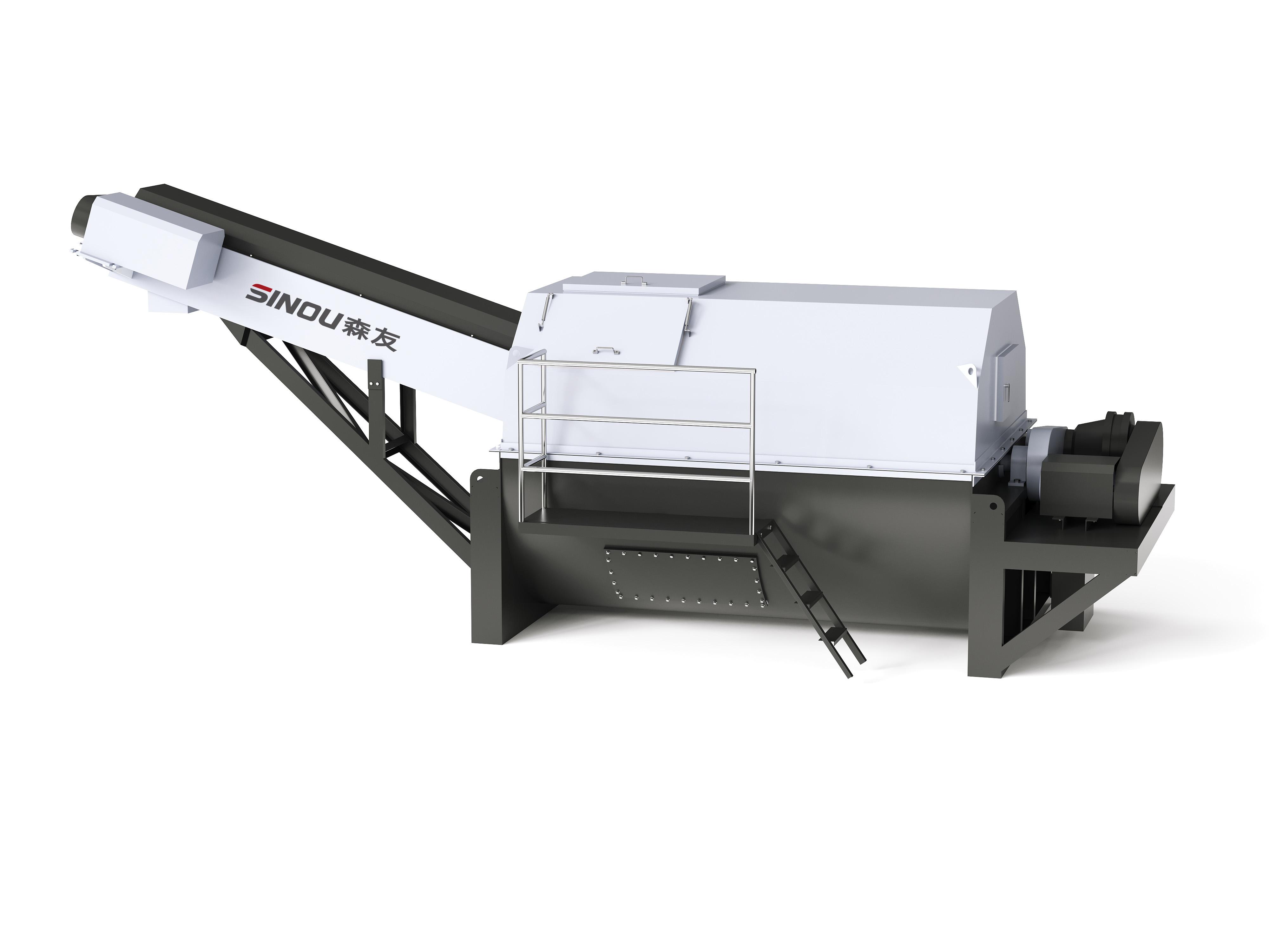
When equipment faces constant grinding, scraping, or high-speed particle impact, material choice becomes the thin line between routine maintenance and catastrophic failure. It’s not enough to pick something “hard”—real toughness means resisting both wear and sudden fracture, often under brutal temperature swings or corrosive atmospheres. In heavy industries, alloys with high chromium content or martensitic steels have been go-to solutions for decades, but they’re rarely a one-size-fits-all answer. Each job demands a careful look at the specific abrasive mechanism: sliding abrasion erodes surfaces differently than gouging from oversized rock, and impact from tumbling media can crush a liner that shrugs off fine-particle erosion.
Ceramics and cermets have carved out a niche where metals fall short. Alumina tiles, for instance, offer incredible hardness and chemical inertness, but they can crack under heavy impact if not supported properly. Tungsten carbide overlays bridge the gap—applied as a weld overlay or as solid inserts, they deliver a cement-like carbide skeleton in a tougher metallic binder, giving surfaces a second life in mining chutes, drilling tools, and mixer paddles. The art lies in matching the right ceramic or composite to the wear pattern: fine-grain structures hold up better under low-impact scouring, while coarser, binder-rich grades absorb energy in high-impact zones without spalling.
Modern surface engineering throws another variable into the mix—treatments like nitriding, boronizing, and laser cladding can transform a run-of-the-mill alloy into a wear-resistant workhorse without changing the underlying component’s toughness. These processes create a hard, diffusion-bonded shell that won’t delaminate like some coatings, and they open the door to using cheaper, more machinable base metals in abrasive environments. Still, the devil hides in the details: aligning coefficient of thermal expansion between substrate and layer avoids micro-cracking, and understanding the exact abrasive—whether it’s quartz sand, metal shavings, or a hot slurry—determines whether you lean into a polished hardface that sheds material or a rough one that traps a protective debris bed. The upshot? No single material wins everywhere; winning strategies come from dissecting the wear system, prototyping with realistic test coupons, and accepting that sometimes the best defense is a replaceable liner that’s tough—not immortal.
Assembly Tactics That Keep Your Washer Running Smoothly
Getting a washer to stay quiet and steady over the years starts with how well its parts are put together. Small adjustments in torque and alignment during assembly can drastically cut down on vibration. Factories that emphasize step‑by‑step bolt sequencing and use calibrated fastening tools help prevent the drum from shifting under heavy loads. This isn’t about flashy engineering—it’s about consistent, repeatable precision that keeps the machine from gradually shaking itself apart.
Another overlooked method is the way suspension springs and dampers are pre‑loaded. Instead of just dropping them in, some lines take the extra minute to pre‑tension each spring to a specific point on the curve. That minor effort means the tub hovers in balance even when you toss in an uneven heap of towels. It also helps the machine shrug off the stress of high‑speed spins without loosening joints or stressing motor mounts.
Sealing and connector placement matter just as much. A subtle twist in mounting the water‑inlet valve or a precise press‑fit of the pump assembly drastically reduces the chance of slow drips that morph into bearing damage later. Routed wiring that avoids rubbing against moving brackets and glued‑then‑clamped hoses represent the kind of assembly habits that separate a washer that hums quietly for a decade from one that clanks and leaks after just a few years.
Incorporating Screens and Classifiers in the Build
When you’re setting up a new plant or revamping an existing line, weaving screens and classifiers into the build from the very start can save you headaches down the road. Instead of treating them as add-ons, think of them as core components that shape the entire flow. A well-placed screen can pull out fines before they reach a crusher, reducing wear and boosting throughput. Classifiers, on the other hand, separate material by size and density, giving you more control over product quality. The trick is to map out the material’s journey early, so these units aren’t just squeezed in but become natural steps that keep everything moving smoothly.
Placement matters just as much as the equipment itself. After primary crushing, for instance, a scalping screen can whisk away oversized chunks that need a second pass, while a classifier might divert mid-size material for further processing. The supporting structure needs to accommodate the vibration and weight of these machines without shaking the whole building apart. Too often, people bolt them onto existing frameworks only to find that access for maintenance is a nightmare. Building with their footprint and service clearances in mind means you won’t have technicians cursing tight spaces later.
Don’t overlook the flow after the sorting happens. Once material passes through a screen deck, the chutes and conveyors downstream must handle the newly divided streams without bottlenecking. A classifier’s discharge points need to lead to the right destinations—whether it’s a stockpile, a mill, or a wash plant. Matching the rhythm of the whole circuit is key: if the classifier works faster than the rest of the line, you’ll create piles that block walkways; if it’s too slow, the whole operation stalls. When you integrate them thoughtfully, screens and classifiers become seamless partners, quietly making everything run better.
Balancing Water Usage and Sand Capture Efficiency
Striking the right equilibrium between water consumption and effective sand retention often feels like a delicate dance. On one side, you need enough fluid to transport proppant deep into the fractures, but over-relying on water can strain local supplies and drive up operational costs. The real challenge lies in designing a system where every gallon is used optimally without compromising the ultimate goal: keeping those fractures propped open to maximize long-term production.
Modern approaches have shifted toward fine-tuning fluid viscosity and flow rates rather than simply flooding the well. By carefully adjusting the rheology, crews can carry sand efficiently with lower overall volumes. Meanwhile, real-time monitoring of downhole conditions helps identify the exact moment when injection can stop—avoiding waste while still ensuring the proppant stays in place. It’s a practical, data-driven answer to the age-old problem of doing more with less.
Beyond the wellsite, water recycling has become a key piece of the puzzle. Treating and reusing produced water not only lightens the burden on freshwater resources but also forces a rethink of how fluids interact with sand particles. Some operators have found that slightly salty, recycled water actually improves proppant suspension in certain formations. Small adjustments like these add up, creating a cycle where efficiency feeds environmental responsibility, and both objectives move forward hand in hand.
Making Sure Your Equipment Passes the Real-World Test
No matter how carefully you follow lab specifications, the actual job site will throw variables at your gear that no controlled test can replicate. Start by putting your most critical pieces through a simulated workflow that mimics real conditions—run the generator with the full load you expect, operate the radio in a concrete basement, or wear the harness while scrambling over uneven terrain. Pay attention to subtle failures: a screen that washes out in direct sunlight, a clamp that jams when there's a little dust, or a battery that drains faster than predicted under heavy use. These snags rarely show up in a sterile testing environment, but they surface quickly the moment you remove the bubble wrap.
Invite the people who'll actually use the equipment to give honest feedback. Someone who spends ten hours a day in the field will spot ergonomic flaws a designer overlooked—the location of a control button, the way a strap digs into a shoulder, or an indicator light that's impossible to see at an angle. Let them handle the gear with muddy hands, in the rain, or after thirty minutes of physical exertion. You'll learn more from five minutes of their grumbling than from a polished product demo.
Finally, keep a detailed log of every hiccup during these real-world trials, and don't dismiss a problem just because it seems minor. A tangled cord or a latch that sticks might be a one-time annoyance in the shop, but under stress it can turn into a dangerous delay. Tweak, retest, and repeat until your equipment holds up against the unpredictable—because out there, the test never really ends.
FAQ
The main structure usually relies on abrasion-resistant steel plates for the drum and chassis, while the paddles or blades are often cast from high-chrome iron to withstand constant friction. Support frames and fasteners are typically made from galvanized steel to prevent rust in wet environments.
Drum angle and speed depend on the desired throughput and material retention time. A tilt of 5 to 7 degrees is common, and rotation is set between 12 and 18 RPM for most medium-sized units. Fine-tuning is done during testing by observing how quickly clean material exits versus the buildup of fines.
Submerged arc welding is preferred for longitudinal seams because it gives deep penetration with minimal spatter. For circumferential joints, a combination of MIG root pass and flux-cored fill ensures strength while reducing distortion. Post-weld heat treatment can also relieve stresses in thicker plates.
Misaligned trunnion wheels cause uneven drum rotation, leading to premature wear on the tires and excessive vibration. Using laser alignment tools during setup keeps the drum concentric and extends the life of both the drive components and the support structure.
A built-in trommel screen section at the feed end helps scalp oversized rocks before they enter the main washing zone. Adding a dewatering spiral at the discharge end reduces moisture content in the final product. Some builders also include adjustable weirs to control the retention of fines.
Spray bars with full-cone nozzles are positioned along the top and at the material entry point to ensure complete coverage. Flow rates are regulated by a manifold with individual valves so operators can adjust pressure for different aggregate types. Recycling water through settling tanks further minimizes consumption.
Guardrails around rotating parts, emergency stop cables along the length of the drum, and non-slip walkways are mandatory. Electrical enclosures must be waterproof and properly grounded. It’s also wise to include a lockout-tagout mechanism on the drive motor to protect maintenance crews.
Yes, it’s possible with careful planning. Many components like the drum, frame, and spray pipes can be fabricated using basic cutting and welding equipment. Critical parts such as bearings and gear reducers can be sourced off-the-shelf. The key is precise jigging during assembly and thorough testing with real material loads to identify weak points early.
Conclusion
Building a reliable sand and gravel washer starts with meticulous groundwork and material selection. Before cutting a single piece of steel, you need to define your throughput targets and the expected particle size distribution of the raw feed. This shapes every subsequent decision, from the drum diameter to the paddle pitch. In abrasive environments, ordinary carbon steel quickly succumbs to erosion. That's why savvy fabricators turn to abrasion‑resistant plate, often with a minimum Brinell hardness of 400, and line high‑wear zones with replaceable urethane or ceramic tiles. Welding procedures must account for these alloys to prevent cracking, and critical stress points benefit from post‑weld heat treatment. Every joint and seam is a potential failure point under constant slurry bombardment, so full‑penetration welds and reinforced gussets become the norm rather than the exception.
Assembly and integration are where the design truly comes to life. A carefully aligned drum, mounted on heavy‑duty trunnion rollers with ample adjustment range, prevents vibration and premature bearing failure. Inside the drum, segmented lifters and spiral flights are bolted rather than welded, making maintenance swaps straightforward. Screens and classifiers don't merely bolt on; they must be tuned to the washer’s output, with the right mesh size and vibration amplitude to avoid blinding while still capturing fine sand. Water management is equally critical in fabrication—incorporating adjustable weirs, multiple spray bars, and a properly sized settling sump helps balance the competing demands of cleanliness and recovery. Finally, no washer leaves the shop without a thorough wet‑test using representative material. Only by scrutinizing bearing temperatures, power draw, water consumption, and discharge gradations under real‑world loads can you confirm that the machine will hold up shift after shift, year after year. When all these elements align, the result is a rugged, efficient workhorse that consistently turns muddy gravel into market‑ready products.
Contact Us
Contact Person: HaiYan
Email: [email protected]
Tel/WhatsApp: +86 18957325588
Website: https://www.senyoubeton.com/